Contactor Wiring Diagram Ac Unit
May 24, 2021 on ac contactor wiring diagram. Wiring between disconnect switch to contactor:
Contactor Wiring Diagram Ac Unit yazminahmed

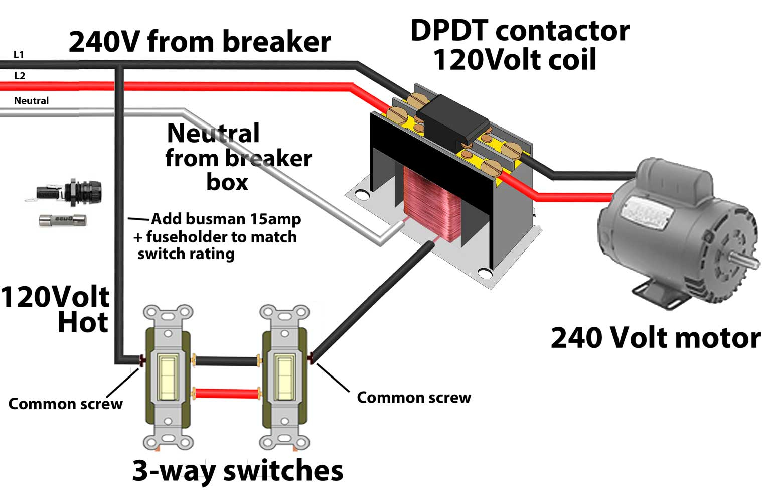
Contactors use 120 volt standard power to energize a magnetic coil, which causes a set of internal contacts to close and provide higher power to the equipment.

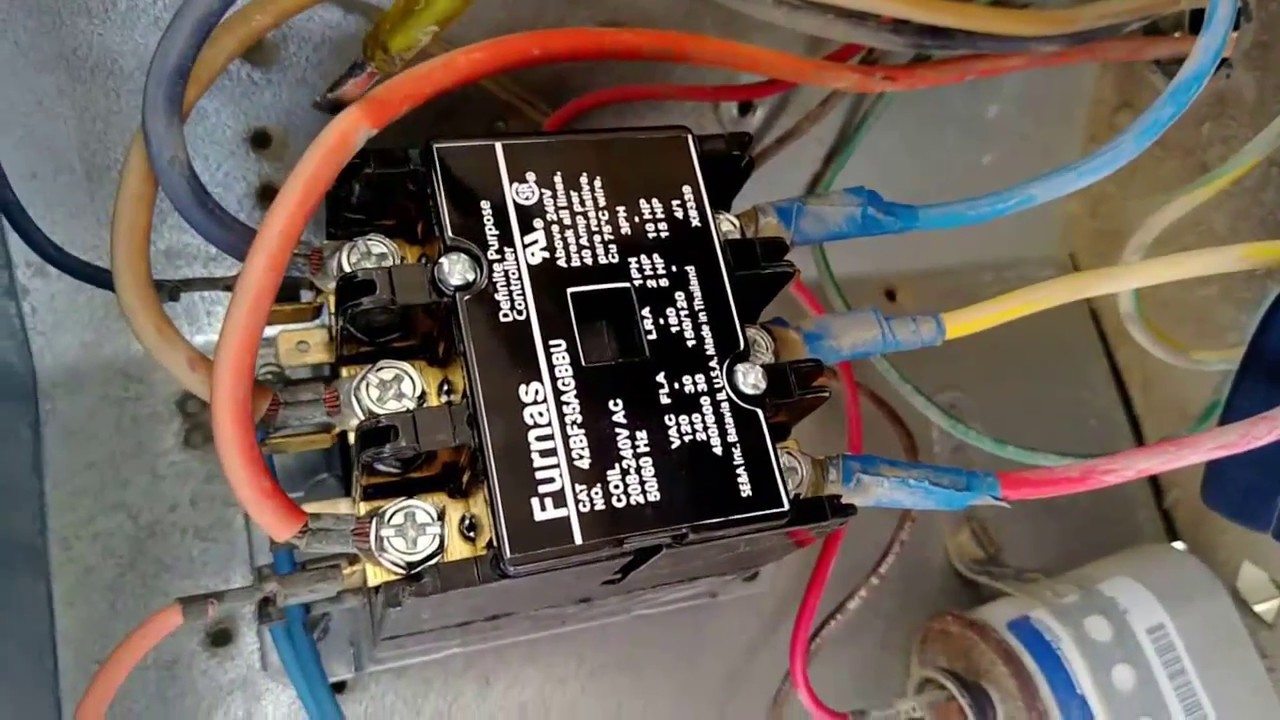
Contactor wiring diagram ac unit. The r terminal is the 24 volt hot feed from the control step down transformer that will power the relay contactor. 40 degree to + 65 degree c. Eaton wiring manual 0611 5 2 contactors and relays 5 5 contactor relays contactor relays contactor relays are.
Supply qty 2 pole contactors, 30 amp, 24 volt $ $ fasco ha $ volt, uv rated each $ $ m. As stated previous, the lines in a ac condenser wiring diagram represents wires. It is a relay switch which directs electricity to the compressor of the air conditioner.
A wiring diagram is an easy visual representation in the physical connections and physical layout of an electrical system or circuit. Typically a contactor is activated by a remote switch or other controlling electrical device. You may be able to know precisely if the tasks should be finished, which makes it easier for you to correctly handle your time and efforts.
Starting with the 240v power supply coming from disconnect a lot of times it’ll be a red and a black wire along with the green wire that is in there. Clever 3 phase contactor wiring diagram start stop 3 phase contactor. A wiring diagram is a simplified traditional pictorial representation of an electrical circuit.
I explain what each of the letter t. Sometimes, the wires will cross. A simple circuit diagram either of the two start buttons will close the contactor either of the stop buttons will open the contactor.
It closes the contacts when something needs to be powered. What is often a wiring diagram? Contactor wiring diagram ac unit.
By vallery masson on may 24, 2021. Crabtree garage consumer unit wiring diagram. There’ll be principal lines that are represented by l1, l2, l3, and so on.
Air conditioning ac contactor control board 1 this diagram is to be used as reference for the low voltage control wiring of your heating and ac system. A wiring diagram is a simplified traditional pictorial representation of an electrical circuit. Make sure that no stray strands are jutting out from the contact block.
Injunction of two wires is generally indicated by black dot at the junction of two lines. Use these tips to learn how to wire a contactor. These voltages must be electrically isolated from the standard 120 volts ac.
Always refer to your thermostat or equipment installation guides to verify proper wiring. Function cjx2 ac contactors provide. Carrier ac unit wiring diagram wiring diagram is a simplified tolerable pictorial representation of an electrical circuit.
Contactor wiring on ac unit 3 power wiring circuits consult serial tag on the unit and select power wiring diagram for the model specified all wires are connected to the terminals on, 1 main circuit wiring the vfd main circuit terminals shown as below figure 1 the Hi, i am trying to find out how to connect the low voltage wires on the new protech contactor i am installing it on a rheem raka 037jaz ac unit. If you wire this side to the battery the contactor will not work.
Carrier heat pump wiring diagram heat pump carrier heat pump thermostat wiring. 240 volts ac and 480 volts ac are commonly used for these large pieces of. Collection of ac contactor wiring diagram.
I purchased a replacement capacitor and installed it and got the a/c working again. A simple circuit diagram either of the two start buttons will close the contactor either of the stop buttons will open the contactornote that one one of the contactor acts as a switch for the start button. Contactor wiring diagram ac unit collections of contactor wiring diagram ac unit sample.
My email address is jwerba1@att.net. And very rarely will it include any internal wiring of the unit. Fasco info sheet the electrical circuit lasts longer when a contactor is used because contact points on a contactor are designed to ambient air temp:
You’ll be able to often rely on wiring diagram as an crucial reference that may assist you to save money and time. Air conditioning ac contactor control board 1 this diagram is to be used as reference for the low voltage control wiring of your heating and ac system. But, it does not imply connection between the cables.
I can send photo's of old and new contactors to your private email if necessary. I became my wife's and kids hero for the day since In addition, wiring diagram gives you time frame by which the projects are for being finished.
And you got your disconnect that’s probably gonna be mounted to the side of the house it’ll either be a. Always refer to your thermostat or equipment installation guides to verify proper wiring. Fig.6 is a typical installation diagram for a residential cooling system.
On ac contactor wiring diagram fasco h230a. Note some ac systems will have a blue wire with a pink stripe in place of the yellow or y wire. On abb contactor wiring diagram.
How to wire an air conditioner for control 5 wires the diagram below includes the typical control wiring for a conventional central air conditioning systemfurthermore it includes a thermostat a condenser and an air handler with a heat source. Many large pieces of equipment are powered directly from high voltage lines. Contactors are used to provide this isolation.
When this post is grounded the contactor is closed. Wiring a contactor is a safe method for controlling electrical power. 240v single pole circuit breaker wiring diagram.
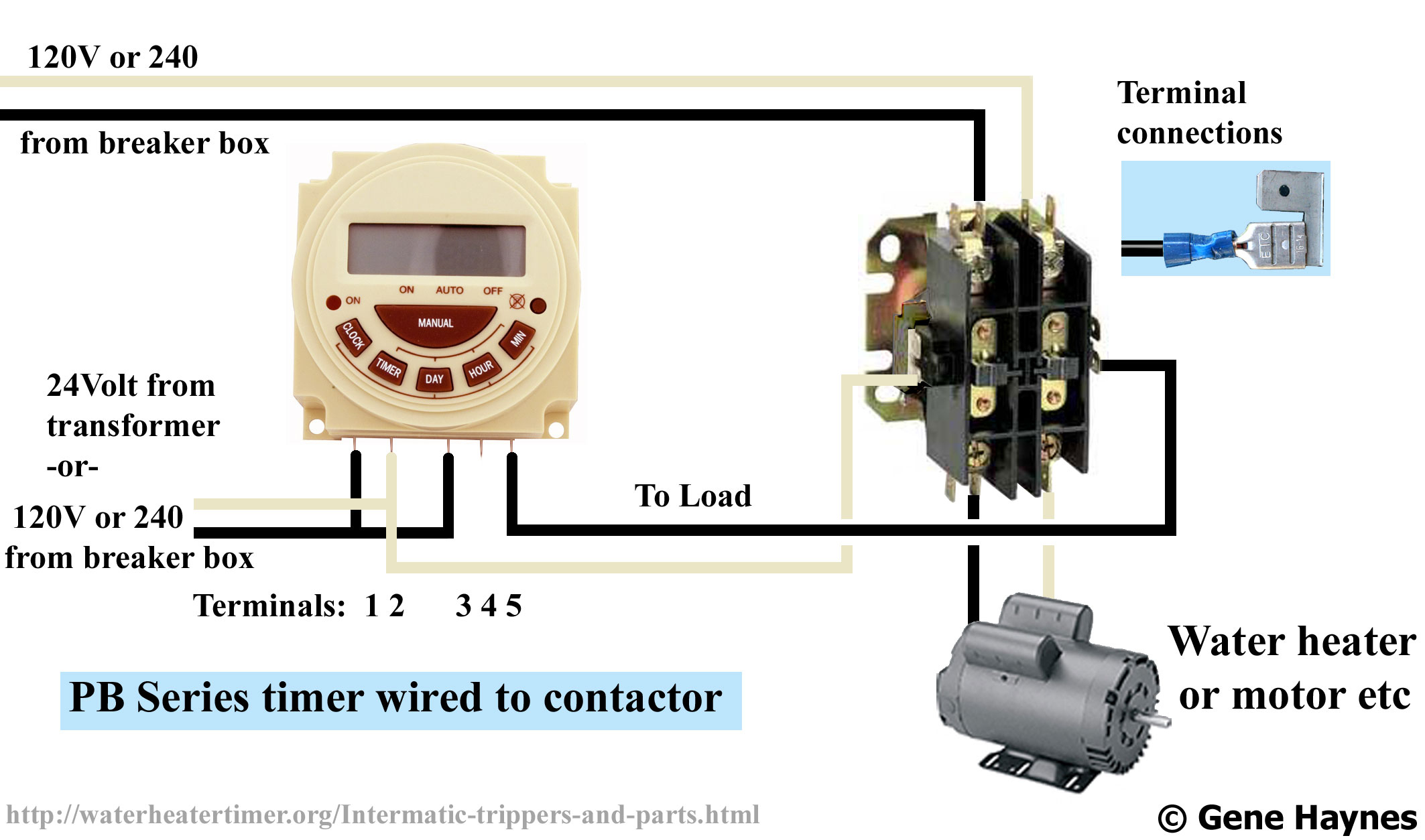
Timer and contactor wiring diagram pdf. When power is not needed, the contactor pulls the electrical contacts apart. Note some ac systems will have a blue wire with a pink stripe in place of the yellow or y wire.
The contactor on the air conditioning unit is a switch that permits or stops power supply to the unit. Timer and contactor wiring diagram.
compressorcontactorwiringdiagram High Performance

Wiring Diagram BTEN AIRCOOL

240 Volt Contactor Wiring Diagram Wiring Diagram
Ac Contactor Wiring Diagram Cadician's Blog
24 volt vs 240 v coil contactor wiring diagram Air
422510103 Contactor Wiring Diagram

Air Conditioning Contactor Wiring Wiring Diagram Networks
Capacitor Contactor Wiring Diagram

Only the red and wires are connected on the ac unit but

Contactor Wiring Diagram Ac Unit For Your Needs

Air Conditioning Contactor Wiring Wiring Diagram Networks
I have a low voltage short keeps blowing the 3 amp fuse

Air Conditioning Contactor Wiring Wiring Diagram Networks

Contactor Wiring Diagram Ac Unit Gallery Wiring Collection

661cj030a Contactor Wiring Diagram

Goodman Ac Capacitor Wiring Diagram

New Contactor Wiring Diagram Ac Unit Diagram, Light

Contactor Wiring Diagram Ac Unit Download Wiring Diagram
Contactor Wiring Guide For 3 Phase Motor With Circuit
